Introduction
The TiCkS (Timing and Clock Stamping) board has been developed as a proposed time-stamping board for CTA, based on the White Rabbit SPEC board (Simple PCIE Carrier). It should be installed in a CTA camera, and accepts trigger signals from the camera trigger electronics which it then time-stamps with nanosecond precision, sending the time-stamp and associated camera event data (TiCkS local event number, optional serial data provided by the camera) to the central DAQ trigger system (SWAT, SoftWare Array Trigger) for coincidence identification. This enables the DAQ to drop non-coincident events.
The TiCkS is a White Rabbit node, so is connected over a single mode fibre to a central White Rabbit switch, through which it is networked at 1 Gbps to standard ethernet. The White Rabbit switch and the WR PTP core firmware (v4.2) allows the TiCkS to be synchronized with the time on the White Rabbit switch, which should itself be synchronized to a central GPS system either directly or as a slave to a master WRS connected to the central GPS system.
The TiCkS firmware has in particular added the functionality to send these data by UDP over the White Rabbit fibre, among other functionalities described below. The TiCkS firmware can also be used as-is on a commercial SPEC board, using an FMC interface board which could an CTA 2xRJ45 FMC or a DIO board, for testing.
The TiCkS board exists in two versions, the first following the CTA UCTS interface interface definition [RD2] including the form-factor, power, and camera trigger interface of 2x RJ45 connectors, while the second has a FMC connector, and can be used with a SPEC DIO (Digital Input/Output). The latter will be placed on the OpenHardware repository, for free general use.
White Rabbit Switch
White Rabbit Switch: https://www.ohwr.org/projects/white-rabbit/wiki/switch White Rabbit Switch Software: https://www.ohwr.org/project/wr-switch-sw/wikis/Release-v501
User Manual
Startup Guide
Developer Manual
SFPs for WRS:

Figure: View of the TiCkS board.
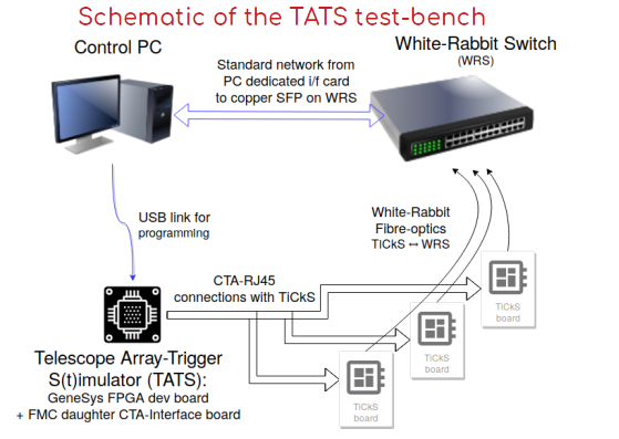
Figure: Schematic block diagram of the TiCkS set-up (on the TATS test-bench, Telescope Array Trigger S(t)imulator)
Reference Documents
A |
Title |
Reference |
Edition |
|---|---|---|---|
RD1 |
Ticks board TDR |
MLST-CAM-RP-0220-APC |
4 |
RD2 |
CTA interface document camera to UCTS |
1 |
Features
1ns precision TDC
UDP Tx/Rx (trigger timestamps sending and slow control)
PPS (Pulse-per-Second) output, on the second marker in absolute time
x MHz output (10MHz standard, other frequencies may be programmed, to be tested)
SPI slave (to receive trigger type and other info from camera), 16 bits
10ms timeout on UDP Tx for low trigger rate (for bunch Tx), start after previous bunch sent
200ns minimum time between events (to avoid re-triggering on showers)
Provides external trigger at programmable time (8ns granularity, <ns accuracy)
SNMP-provided monitoring of parameters
Operational States
- Synchronizing:
On power-up, the TiCkS starts in the Synchronizing state and transitions to the Reset/Standby state once the WR clock is synchronized to the master.
- Reset/Standby:
Arriving in the Reset/Standby state from Synchronizing, the TiCkS produces PPS pulses as soon as possible, as required for some cameras.
On reception of a
Resetcommand over UDP (see section 6) the TiCkS goes into this mode.In this state, no trigger inputs are accepted, and the event counters (read-out and busy counters) are set to zero
- Ready:
On reception of a
GetReadycommand, the TiCkS goes into Ready stateThe TiCkS does not accept triggers in this state
The TiCkS waits for the next PPS, which send it into the Running state
- Running:
On transition into Running state, the TiCkS immediately sends an “External Trigger” signal to the Camera trigger electronics, as a signal for it to zero its counters
The TiCkS accepts triggers from the camera in Running state, and time-stamps them, including SPI if this is enabled
On reception of a Reset command, the TiCkS goes back into Reset/Standby state
Signal characteristics
The TiCkS input/output to the CTA Camera’s trigger electronics follows the CTA-defined interface [1], sending/receiving LVDS signals over 2 RJ-45 connectors.
All LVDS signals follow the standards ANSI/TIA/EIA-644-1995 and IEEE 1596.3 SCI-LVDS.
The trigger signal received for time-stamping should be longer than 20ns.
The 10MHz signal sent from the TiCkS should be synchronized to the 1PPS (pulse-per-second), to within ~8ns (arriving at or after the PPS). The duty-cycle is set to 50%.
The SPI is used in Master-Slave mode where the Camera is the master and the TiCkS is the slave, with 16 bits width. The clock polarity CPOL = 0 should be used (see https://en.wikipedia.org/wiki/Serial_Peripheral_Interface#/media/File:SPI_timing_diagram2.svg). If the SPI message does not arrive within 500ns, its value is set to 0xAA and the TiCkS ignores any late-arriving SPI messages.
The external trigger sent by the TiCkS is 40ns in length (can be modified with firmware resynthesis)
Set up
This firmware has been developed to be used on stand-alone TiCkS used as a node. It also needs a White Rabbit Master: either a White Rabbit Switch connected to a PC or a SPEC in a PC’s PCIe slot. The first one is preferred as it is closer to the final implementation for CTA (indeed, the second can only be done on an outdated OS):
PC with Scientific Linux 7 or CentOS 7 connected to a White Rabbit switch through copper SFP.
TiCkS or SPEC+ RJ45-FMC connected to the WR switch through SFPs + optical fibre.
DHCP server on the PC configured according to CTA documentation.
TiCkS has the standard CTA interface (2xRJ45) or one SPEC + 2xRJ45 FMC can be used. For the trigger signal input, TiCkS requires that this be >20ns in width in order for both the time-tagging and the increment of the event counter to function correctly.
Note that on Power-up, the TiCkS starts in the Reset/Standby state, and should produce PPS pulses as soon as possible (once the WR clock is synchronized to the master), as required for some cameras. Note: The UCTS will not produce PPS pulses unless and until it is synchronized to the master. This avoids having an unsynchronized PPS pulse being distributed.
TiCkS configuration
Both Rx and Tx are implemented. Tx is used to send timestamps and some additional data (see data format section). Each UDP frame is at most 350 bytes, with the data payload of 12 bytes per event plus a bunch tailer of 20 bytes, for giving a payload size of are 308 bytes for 24 events. This size may be smaller if the Tx timeout is reached, with fewer events per bunch transmitted. Rx is used for the reset counters protocol and for slow control.
Some functionalities of the TiCkS board can be configured by sending a 64-bit word over UDP.
The 4 LSB bits choose the function and 60 other bits are the value to set (little endian)
0x”0” for run/reset counters
0x”1” to set the MAC address of the destination
0x”2” to generate an external trigger at a given date/time
0x”3” to set trigger throttle value
0x”4” to set IP destination address for data instead of that derived from the TiCkS IP address obtained from bootp
0x”5” to enable/disable SPI reception (in this case, the SPI data field is set to 0x0000)
0x”6” to change the destination port for data instead of the default of 55000 in TiCkS
Note: these commands can come from any IP, only the port is checked to be the correct one. The commands can be sent while the TiCkS is acquiring triggers, but as there is a very low probability that the command reception can interfere with data taking (as measured in tests) it is recommended to send these commands only in the Reset mode (except for the Reset command itself).
UDP Network Configuration
The firmware uses bootp to get its IP address. The destination IP (PC connected to the switch running the CDTS-server or equivalent to receive the data) address is computed from this address. The first 22 bits of the TiCkS IP address obtained through bootp are kept, while the last 10 bits are replaced with 11-1111-1010 (3.250). For example if TiCkS obtained 10.10.128.99 IP address with bootp, packets from the TiCkS will be sent to 10.10.131.250.
Defaults are:
- TiCkS
IP address 192.168.0.100
TiCkS Rx port (for receiving commands from DAQ) hard-coded currently to 55010
MAC address is unique (from temperature sensor)
- DAQ PC or SPEC in PC
IP address 192.168.3.250 (given derivation from TiCkS IP address)
TiCkS Tx port (for receiving time-stamps from TiCkS) default is 55000 (modifiable by command)
MAC destination address 00:00:00:00:00:00
In addition, one needs to issue a 64-bit word through UDP each time TiCkS is powered up, to ensure that the TiCkS also receives the MAC destination address (PC address):
4 LSB are set to 0x1 (see previous) next 48 bits are MAC destination address
- 64 bits command example to set MAC destination address (CDTS server)
if PC MAC address = 68:05:ca:3a:8f:28, send ‘FFF6805ca3a8f281’
Counter Reset Procedure
A counter reset procedure has been implemented which uses UDP Rx capability of the TiCkS board. The counters for Event trigger, Busy trigger and PPS are the only ones involved in the reset procedure (i.e., when referring to “the counters” below). Note that the PPS and x MHz signals continue to be sent to the Camera during the reset procedure.
The default state at power-up is a reset state, with these internal counters of the TiCkS in reset, as is the TDC. No data are sent, only 20 bytes of bunch tailer with slow control information every 10ms (currently a hard-coded delay, can be modified with firmware resynthesis). To initialize counters and TDC, a “GetReady” command must be sent to the TiCkS over UDP.
When 0xFFFFFFFFFFFFFFF0 is sent to TiCkS, this issues the command “Get Ready” described in the Reset procedure developed for LST/NectarCam, where the counters and TDC will start and an “External trigger” will be sent to the Camera just after the next PPS (#0). The PPS after that is counted as #1. The camera, having also been put into “Get Ready” mode by the controller, uses this external trigger signal to start its event, busy, and PPS counters.
If 0xFFFFFFFFFFFFFF00 is sent, this issues the command “Reset/Standby”, where the counters will stop and be set to zero, and TDC will also stop.
The reset state can be checked by reading bit-14 in the bunch tailer, which is set to ‘1’ if TDC and counters are enabled, ‘0’ if stopped and set to zero.
Generate an external trigger
- An external trigger can be generated at a date (8ns granularity, <1ns accuracy) sending that date over UDP.
4 LSB are set to 0x2 (see previous), the next 52 bits are the date at which to generate an external trigger
28 bits from 4 to 31 are 8ns part of time, within the second
25 bits from 32 to 56 and is the seconds part of the date (TAI)
Note, the seconds part of the time can be generated easily by the Linux “date” command (!!as long as the DAQ PC is set to the current time, e.g. with NTP), such as:
    date +%s        # Current date in seconds
    date +%s --date 'now'   # same
    date +%s --date '1 minute'      # Date in 1 minute
    date +%s --date '1 hour'        # Date in one hour
    date +%s --date '17:20:10'      # Date at given time
    date +%s --date '18 jan 2016 17:20:10 UTC'      # Date at given date/time
...
    date -ud @2000000000 # The inverse, convert Linux date to human-readable format
Trigger Throttle
A trigger throttle, where events are not written to the FIFO if the time between the first and last event in the bunch is less than 200us (configurable, see above) has been implemented and tested. In other words, the TiCkS will keep writing in the FIFO if the time difference between first and last trigger of bunch > 200us (default). This default corresponds to the programmed value x”30D3” / 12488, which is 200us with clk_sys, at 62.5MHz. The throttle is currently enabled or disabled at the synthesis of the firmware.
Some cameras prefer to handle this in their trigger electronics, since now the B-xST-1285 requirement imposes a trigger rate cap on them (e.g. <30/14/1.2 kHz in 100ms for LST/MST/SST), so in future this may be programmable remotely (TBD).
Data format
Bunches of 24 events (i.e., up to 24, if no time-out; fewer if time-out)
308 bytes of data payload if no time-out (24 x 12 bytes + 20 bytes) SPI data width is 16 bits, and can contain Event-type data and other information (e.g. Stereo Trigger pattern, for those telescopes which have this). Each bunch is self-contained, and does not depend on the data in previous or following bunches, though the individual event information must be reconstructed using the information in the tailer.
Event data, 96 bits (12 bytes)
Bits |
Content |
|---|---|
95 downto 80 |
SPI data 16 bits set to ‘0’ when there is no SPI input |
79 downto 72 |
event read-out counter 8 bits LSB (max 255/bch) |
71 downto 64 |
event busy counter 8 bits LSB (max 255/bch) |
63 downto 62 |
PPS counter 2 bits LSB (max 4 in bch) |
61 downto 60 |
seconds 2 bits LSB (max 4 in bch) |
59 downto 59 |
1 flag, Busy |
58 downto 58 |
1 flag, SPLL locked & local time sync to Master |
57 downto 32 |
clk counter 26 bits (max 67M-clock, or 670MHz if 100ms bch time-out) |
31 downto 4 |
8ns timetag, 28 bits |
3 |
not used, set to ‘0’ |
2 downto 0 |
TDC 1ns precision 3 bits |
Bunch tailer, 160 bits (20 bytes)
Added to each bunch of 24 events (up to 25, if no time-out) before sending or sent after time-out for slow control if there is no trigger, so corresponds to the counters for the last event. (Modif 20190606, format v0.6: Except for the seconds, where this value is for the last read-out event, since this is the only common counter not duplicated for read-out / busy). Note: The tailer contains the full counter, not just the MSB. So if only the tailer is read, the final read-out and busy event counter can be known, without needing to decode the individual events.
bits |
Content |
|---|---|
159 downto 128 |
bunch counter 32 bits |
127 downto 96 |
event counter 32bits |
95 downto 64 |
busy counter 32 bits |
63 downto 48 |
PPS counter 16bits (16bits total → 18h of PPS) |
47 downto 16 |
seconds 32 bits (32bits total → 136yrs of seconds) |
15 |
flag for tm_time_valid (SPLL lock & local time synch to Master) |
14 |
flag for rst_cnt_ack (counters and TDC reset) |
13 downto 8 |
not used, set to ‘0’ |
7 downto 0 |
version # (xxxx.yyyy for major.minor version) |
Description of the different fields
- For the events within the bunch:
“Seconds” is the 16 least significant bits (LSBs) of the WR time stamp (so it should be that part of TAI, for a WR-Switch up so that it is running an NTP client). If NTP is not running on the WR-Switch, it will be the LSB part of the seconds since the switch booted up (we recommend to set up NTP on your switch… see REFERENCE??).
“PPS counter” is the count of the PPSs since the reset/GetReady of the TiCkS.
“8ns tag”, is the time-stamp to within 8ns since the last PPS
“1ns tag”, is the 1ns part of the time-stamp within the 8ns above.
“Time valid”, is the value of that flag in the WR-node/TiCkS at the time of the time-stamp.
“SPI” should be the pattern sent from the TIB to the TiCkS over the SPI link (so, telescope triggered pattern and event type). (to be tested in detail). Modif 20190606, format v0.6: If the TiCkS is set in more “no-SPI”, then “0x0000” is put. If the TiCkS is in mode SPI, but the SPI reception times-out, then “0xAAAA” is put:
- For the tailer (besides the MSBs of some fields above):
“Time valid” is the same as described above (it is repeated in the tailer, in case no triggers are coming in so that this can still be monitored).
“Flag for counters & TDC enable reset”, is set if the counters and TDC are enabled, zero otherwise
Receiving software
A prototype version of the CDTS-Server or Bridge software – which receives the UDP packets from the TiCkS-UCTS and sends them on via TCP to another address/port – is given on the CTA SVN server [3] and on git: https://gitlab.in2p3.fr/mdpunch/ticks. Further details are given in Appendix A. This software has been extensively tested. Alternatively, Wireshark or tcpdump can be used to capture the raw packets.
SNMP
SNMP is now implemented in WRCore since v4, so it is possible to get status information from WR core itself (see WR user’s manual for details). SNMP can also get information from the TiCkS, with the information already provided in the tailer (counter values, PLL lock, reset status) as well as the destination IP and MAC address, and other values (To Be Defined).
This will allow the monitoring of the TiCkS from other points besides the PC which receives the data. The functionality is implemented, but parameters to be monitored and the monitoring software have to be defined.
In order to test SNMP functionality, follow the procedure as in the wrpc-user-manual-v4.2.pdf. Set the SNMP_OPT environment variable to use the appropriate “MIB” file, then execute the “snpmwalk” command with this, e.g.: SNMP_OPT=”-c public -v 2c -m WR-WRPC-AUX-DIAG-MIB -M +/home/cta/Documents/UDP_test/wr-coresv4.2/snmp 10.10.3.108” snmpwalk $SNMP_OPT wrpcCore
If the card at the given address responds, it will give a list of values, for example the TemperatureValue. If the address does not respond, then either the card is not present at that address, or is not operational. CC needs to modify the values avaibable by SNMP, and also the MIB file for interpreting this.
- Besides the standard WR SNMP monitoring variables which can be found at TkXXXX ???, the specific variables which can be monitored for the TiCkS are as follows:
IP destination address
MAC destination address
port destination
readout event counter
busy event counter
firmware version (in next firmware version, after firmware commit 73b562a Tk: to be updated with version #)
throttler value (see above for default)
throttler implemented (at synthesis)
WR time valid
SPI enable
Future developments for Configuration & Operation
Some options for future developments are being explored, but we consider that the essential functionality of the TiCkS responds to the needs.
Time-scales considerations
The White Rabbit is an extension of PTP, so uses the same conventions as PTP.
From https://en.wikipedia.org/wiki/Precision_Time_Protocol:
PTP typically uses the same epoch as Unix time (start of 1 January 1970).[note 1] While the Unix time is based on Coordinated Universal Time (UTC) and is subject to leap seconds, PTP is based on International Atomic Time (TAI). The PTP grandmaster communicates the current offset between UTC and TAI, so that UTC can be computed from the received PTP time.
TAI and GPS time are strictly monotonic, with no gaps or overlaps due to leap seconds as un UTC.
TAI is currently (in January 2020) ahead of UTC by 37 seconds. The zero of GPS time is defined as being 0h on 6-Jan-1980. TAI is always ahead of GPS by 19 seconds.
For PC applications, we should use a linux kernel clock which is monotonic and/or based on TAI.
So, the recommendation for PC applications is to use is to use a a linux kernel clock which is monotonic and/or based on TAI. Any recent NTP daemon can set the kernel’s TAI_OFFSET variable. Then we can use use clock_gettime(CLOCK_TAI, struct timespec *tp); (which is supported by linux kernel’s >3.10) or equivalent, to get the TAI time.
As in the SWAT manual, the instructions for NTP are below:
NTP’s configuration file (usually /etc/ntp.conf) must include the following directive :
leapfile /usr/local/etc/leap-seconds.list
Add a cronjob to periodically (once per day) update leapfile (https://hpiers.obspm.fr should be reach- able). The cronjob could be:
#!/bin/bash
#
# this is : /usr/local/sbin/ntp-get-leapseconds-file.sh
#
# copy official TAI-TC leap seconds table
# remember to add to /etc/ntp.conf line:
#
# leapfile /usr/local/etc/leap-seconds.list
#
#
crontab job :
# 3 14 * * * /usr/local/sbin/ntp-get-leapseconds-file.sh > /dev/null 2>&1
wget -O /tmp/leap-seconds.list.tmp https://hpiers.obspm.fr/iers/bul/bulc/ntp/leap-seconds.list
if [ 0 = $? ]; then
         echo "OK"
        /bin/mv /tmp/leap-seconds.list.tmp /usr/local/etc/leap-seconds.list
        /bin/chmod 644 /usr/local/etc/leap-seconds.list
        chown root:root /usr/local/etc/leap-seconds.list
fi
Firmware Versions
A table of the latest distributed firmware versions is given here: https://forge.in2p3.fr/projects/ctaactl/wiki/UCTS-TiCkS
After mid-2020, the new versions will have a firmware version number which will be accessible by SNMP, which will be added to this table.
All firmware versions are kept under version control, at: https://gitlab.in2p3.fr/cedric-champion/TiCkS_wr-coresv4/
Updating of the Firmware (if needed)
Normally, the operation to update the firmware in the PROM flash memory should not be necessary, but if it is, the tools required are:
Either:
iMPACTsoftware from Xilinx, or
xc3sprogsoftware (see below)a USB-blaster (USB to Jtag).
The versions of the TiCkS board distributed after spring 2020 use the Macronix MX25L3233FMI-08G flash memory which is pin-to-pin compatible with the obsolete M25P32 memory (as used on the SPEC board), see https://www.ohwr.org/projects/conv-ttl-rs485-hw/wiki/obsolete-components.
That website gives all the instructions for programming the board, either with
the Xilinx iMPACT software or the much more convenient xc3sprog
(which is planned to be used on the remote reprogramming board).
A branch of the xc3sprog software with a minor change
to take into account the new flash can be found at:
https://github.com/mdpunch/xc3sprog.
We note just a bug with the Platform Cable USB II from Xilinx. It is sometimes necessary to unplug/replug the Platform Cable USB II to reprogram the board, after a first test or a scan. (But, it works fine with the FDTI USB/JTAG chip which will be used on the remote reprogramming board)
When using Xilinx iMPACT, select the equivalent density Micron N25Q device
instead of the desired Micron MT25Q device or Macronix device,
see the Macronix Application Note AN-0245:
http://www.macronix.com/Lists/ApplicationNote/Attachments/1903/AN0245V2%20-%20Using%20Macronix%20Serial%20Flash%20with%20Xilinx%20iMPACT%20Tools.pdf
To avoid the error message, set the following operating system environment variable
export XIL_IMPACT_SKIPIDCODECHECK=1
which instructs the iMPACT tool to bypass the ID check,
allowing the programming operation to proceed.
Then launch Xilinx iMPACT tool.
—
Obsolete
If you have an “mcs” file (“microcontroller series”), this can be flashed directly to the PROM in the standard Xilinx procedure, and specifying the PROM memory type (m25p32).
You may be starting from a bitstream “bit” file (which is a file which can be loaded directly into the FPGA and will run, but is lost when you power down). In this case you first have to create the “mcs” file. The procedure uses the PROM file formatted wizard in Xilinx Impact, and is also described with more relevant SPEC/TiCkS details in the White Rabbit core v3 user’s manual (below). Note that you need to add a “non configuration file” from the White Rabbit Core Collection to set up the filesystem on the PROM (using version sdbfs-standalone-160812.bin not version sdbfs-flash.bin on the OHW site).
Tips and Tricks
Normally, the IP address for a given “telescope” should be fixed, which can be done by setting the bootp table such that the MAC address of the TiCkS card corresponds to the IP address desired for that telescope. Otherwise, bootp could be left to distribute available addresses, and the relation could be confusing.
- How to check what cards are available at what addresses / ports?
sudo tcpdump -i enp4s0
Gives list of packets on the relevant interface, UDP packets which are of length 308 are probably bunches from TiCkS cards
sudo nmap -sP 10.10.3.250/24
Here
10.10.3.250is the address of the network card attached to the WR switch-overGives MAC addresses and IPs for connected devices/cards
- How to look at the data from a particular card:
sudo tcpdump -X -n -e -i enp4s0 host 10.10.3.107
Gives data in various formats.
- How to see the terminal on the card (if USB is connected):
sudo minicom -D /dev/ttyUSB0
Then type “gui” (Esc to exit gui, Ctrl-A Q to quit minicom)
Whichever USB device is relevant to the card (undefined a priori), but minicom gives the IP address then.
- How to see what’s on the etherbone registers map
eb-ls udp/10.10.3.99
For example check IP address (obtained from DHCP server)
- ::
#eb-read udp/$(IP_TiCkS) 0x20718/4
Documentation
[1] CTA Interface document camera to UCTS: Interface database on Sharepoint
[2] CTA Network document: CDTS Network Bridge
[3] Software prototype for CDTS server: CTA SVN repository
[4] White Rabbit core v4.2 user’s manual, on Open hardware website: WR corev4.2
Document History
Version |
Date |
Modification History |
Pages/Chapter |
|---|---|---|---|
0 |
2018-05-09 |
Creation |
|
1.0 |
2018-07-01 |
First draft |
|
1.1 |
2019-03-26 |
Updated some points, notably for command 0x”6” to change the port |
|
1.2 |
2020-02-11 |
Added a section on “Operational states” |
|
1.3 |
2020-02-21 |
Added a section on “Time-scales considerations” |
|
1.4 |
2020-05-07 |
Added an appendix on “The Question of Calibration” Modified section on “Firmware update” |
Appendix C Section “Firmware update” |